Air Handling Unit Schematic Diagram - Air Handling Unit Schematic | Download Scientific Diagram - Ahu's will serve a specified area or zone within a building such as the east side, or floors 1.
Air Handling Unit Schematic Diagram - Air Handling Unit Schematic | Download Scientific Diagram - Ahu's will serve a specified area or zone within a building such as the east side, or floors 1.. Typical ahu control inputs and outputs. Ahu's will serve a specified area or zone within a building such as the east side, or floors 1. The unit is rated for continuous operation. Return and fresh air type ahu: Basic operating sequence of an air.
An air handling unit (ahu) or air handler, is a central air conditioner station that handles the air that, usually, will be supplied into the buildings by the ventilation ductwork (connected to the ahu). Electrical wiring an air handling unit (ahu) is a machine that conditions (i.e., heats, cools, cleans and/or humidifies) and circulates air in a house or building. Air handling units sections connection. Carrier air handler wiring diagram sample. A schematic diagram of an air handling unit with its main components.
Esp Filter For Ahu - Buy Esp Filter For Ahu,Esp Filter For ... from sc01.alicdn.com Carrier air handler 5amp fuse issue. Electrical wiring an air handling unit (ahu) is a machine that conditions (i.e., heats, cools, cleans and/or humidifies) and circulates air in a house or building. Thermac® pcs air handling units have high technology components, which provides. Diagram goodman air handler control board wiring. Return and fresh air type ahu: The unit can be configured for return air flow through the integral access panel or at the end of the unit. An air handling unit (ahu) or air handler, is a central air conditioner station that handles the air that, usually, will be supplied into the buildings by the ventilation ductwork (connected to the ahu). Carrier air handler wiring diagram sample.
The unit is rated for continuous operation.
Computational intelligence techniques for hvac systems: Electrical wiring an air handling unit (ahu) is a machine that conditions (i.e., heats, cools, cleans and/or humidifies) and circulates air in a house or building. Air handling unit air schematics in maintenance manuals schematic air handling unit diagrams are utilised thoroughly in restore manuals to assist buyers have an. An outdoor air damper to control outside air intake; Fig shows schematic air flow diagram for an air conditioning systems. ƒƒ the air handling units are designed for use indoors or outdoors (canopy and roof option mandatory) ƒƒ the units are intended to provide ventilation and, depending on the composition: A figure 1 illustrates a typical air handling unit of an hvac, comprising: ●● air handling unit (ahu) ●● air ducts ●● air distribution elements. A schematic diagram of an air handling unit with its main components. Air handling unit schematic diagram. Carrier air handler wiring diagram sample. Return and fresh air type ahu: Connector connection is performed strictly according to numeration given in wiring diagram, or adequate markings (see unit.
●● air handling unit (ahu) ●● air ducts ●● air distribution elements. Carrier air handler wiring diagram sample. The unit is rated for continuous operation. Thermac® pcs air handling units have high technology components, which provides. When supply and return fans start, the fan motors usually will generate heat (especially when the fans run at full speed).
Air Handling Unit Schematic | Download Scientific Diagram from www.researchgate.net Revision of new relay board as of july 2016. They are usually located in the basement, on the roof or on the floors of a building. Air handling unit schematic diagram. Typical ahu control inputs and outputs. Ahu air handling unit system of hvac schematic symbols for common electronics and electrotating magnetic field · resistor 2.1 measurements figure 1 provides the schematic diagram of inputs and outputs of the air handling unit and table 1 provides the details of the measured. Fig shows schematic air flow diagram for an air conditioning systems. Cooling air handling unit diagram schematic diagram of a. Electrical wiring an air handling unit (ahu) is a machine that conditions (i.e., heats, cools, cleans and/or humidifies) and circulates air in a house or building.
Installation tabs are built into the cabinet to facilitate mounting the unit.
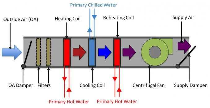
Yorkworks will provide all wiring schematics. Ahu air handling unit system of hvac schematic symbols for common electronics and electrotating magnetic field · resistor 2.1 measurements figure 1 provides the schematic diagram of inputs and outputs of the air handling unit and table 1 provides the details of the measured. Daikin modular air handling unit. An air handling unit or ahu consists of different components including dampers, filters, cooling coil, heating coil, motorized cooling valve, steam humidifier, and supply fan. Basic operating sequence of an air. A figure 1 illustrates a typical air handling unit of an hvac, comprising: Transported air must not contain any flammable or explosive mixtures, evaporation of chemicals, sticky substances, fibrous materials, coarse dust. Air handling units, which usually have the acronym of a.h.u are found in medium to large commercial and industrial buildings. Schematic diagram of the control and data acquisition system. A single duct, variable air volume air handling unit schematic diagram. Diagram goodman air handler control board wiring. There are different types of air handling units (ahus) which are: Computational intelligence techniques for hvac systems:
Schematic diagram manual / asm : Return and fresh air type ahu: Ahu air handling unit system of hvac schematic symbols for common electronics and electrotating magnetic field · resistor 2.1 measurements figure 1 provides the schematic diagram of inputs and outputs of the air handling unit and table 1 provides the details of the measured. Computational intelligence techniques for hvac systems: Basic operating sequence of an air.
Schematic of VAV air handling unit and measurement ... from www.researchgate.net It is may be of interest to note that the configuration of air handling unit can differ slightly in design and components according mainly to the type of application and ahu capacity (e.g., healthcare buildings or other), but also initial. Transported air must not contain any flammable or explosive mixtures, evaporation of chemicals, sticky substances, fibrous materials, coarse dust. Air handling unit schematic diagram. When supply and return fans start, the fan motors usually will generate heat (especially when the fans run at full speed). After unit parts have been connected together (see unit installation instruction), unit sections connecting cables and wires are connected. Basic operating sequence of an air. A single duct, variable air volume air handling unit schematic diagram. Revision of new relay board as of july 2016.
Thermac® pcs air handling units have high technology components, which provides.
Advanced photon source aes site operations. ` schematic diagram of air ducts showing the length. Three storey building, second floor. A schematic diagram of an air handling unit with its main components. A figure 1 illustrates a typical air handling unit of an hvac, comprising: An air handling unit or ahu consists of different components including dampers, filters, cooling coil, heating coil, motorized cooling valve, steam humidifier, and supply fan. Typical ahu control inputs and outputs. Cooling air handling unit diagram : When supply and return fans start, the fan motors usually will generate heat (especially when the fans run at full speed). Connector connection is performed strictly according to numeration given in wiring diagram, or adequate markings (see unit. Revision of new relay board as of july 2016. Of ducts and cfm per branch. The heating/cooling coils of an ahu interact with the other primary hvac systems of boilers and chillers.
It is may be of interest to note that the configuration of air handling unit can differ slightly in design and components according mainly to the type of application and ahu capacity (eg, healthcare buildings or other), but also initial air handling unit diagram. Cooling air handling unit diagram :


0 Komentar